| Chilled Water and Direct Expansion |
|
| |
|
|
| Model: CD-DP/NP |
|
|
|
|
| |
|
|
|
|
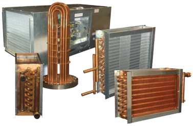 |
Standard Box Construction
• 16-gage galvanized sheetmetal housing (unpainted)
• 1 "/1 1/2 Ibs. sq. ft. insulation open face (not exposed to the air stream)
• Panel access to the headers and return bends
• 16-gage galvanized drain pan with mastic coating (stainless steel drain pan is available as an option)
• 1" FPT drain coupling in drain pan
• Offset fin pack to maximize per formance and drainage
• 1 1/2" duct flanges on entering and leaving airside of coil housing
• 6" connection stub outs on all coil models
• Sloped drain pan |
|
| |
| Standard Type |
| Row |
1 |
2 |
3 |
4 |
6 |
8 |
10 |
| CD with Drain Pan |
15" |
15" |
18" |
18" |
20" |
24" |
28" |
| CD without Drain Pan |
8" |
8" |
8" |
10" |
12" |
16" |
18" |
|
| |
|
|
|
|
Standard Box Sizes Available
• Finned height = 12" to 48" in 1 1/2" increments
• Finned length = 12" to 128" in 1/2" increments
Recommendations: Face Velocities and Static Pressure
• Maximum of 500 FPM - up to 48" FH x 120" FL with 8 FPI or less
• Maximum of 450 FPM - up to 48" FH x 120" FL with 9 FPI or greater
The standard coil box design will accept either a blowthrough or draw-through application.
The maximum static pressure acceptable would be 2" w.g. positive or -1 " w.g. negative
(measured on inlet side of coil). Localized areas of higher velocities can cause water carry over and must be avoided. |
| |
|
|
|
|
Options:
• FH up to 72"
• FL up to 180"
• Intermediate Drain Pan
• S.S. Drain Pan
• Multiple Coils
• Welded Steel Bases |
• Painted Boxes
• Double Wall Construction
• Mounted Filter Rack
• Mounted TXVs
• Mounted Hot Gas By-Pass Connection
|
|